741 OPERATIONAL AMPLIFIER

The Operational Amplifier is probably the most versatile Integrated Circuit 
available. It is very cheap especially keeping in mind the fact that it contains
several hundred components. The most common Op-Amp is the 741 and it 
is used in many circuits.
The OP AMP is a ‘Linear Amplifier’ with an amazing variety of uses.
Its main purpose is to amplify (increase) a weak signal - a little like a
Darlington Pair.

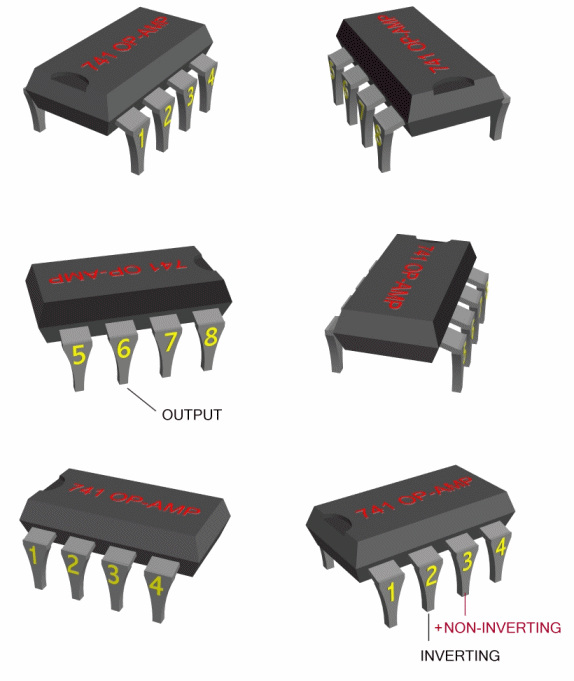
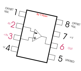
The OP-AMP has two inputs, INVERTING ( - ) and NON-INVERTING (+),
and one output at pin 6.
The chip can be used in a circuit in two ways. If the voltage goes into pin two 
then it is known as an INVERTING AMPLIFIER.
If the voltage goes into pin three then the circuit becomes a NON-INVERTING 
AMPLIFIER.. 


THE 741 IS USED IN TWO WAYS

1. An inverting amplifier. Leg two is the input and the output is always
reversed.

In an inverting amplifier the voltage enters the 741 chip through leg two and
comes out of the 741 chip at leg six. If the polarity is positive going into the
chip, it negative by the time it comes out through leg six. The polarity has
been ‘inverted’.

2. A non-inverting amplifier. Leg three is the input and the output is
not reversed.

In a non-inverting amplifier the voltage enters the 741 chip through leg three
and leaves the 741 chip through leg six. This time if it is positive going into
the 741 then it is still positive coming out. Polarity remains the same.


1. An inverting amplifier - Leg two is the input and the output is always
reversed or inverted.
2. A Non-inverting amplifier - Leg three is the input and the output is
not reversed.
Opposite is a diagram of an INVERTING AMPLIFIER. This

means that if the voltage going into the 741 chip is positive, it is negative when it comes out of the 741.
 In other words it reverses polarity (inverts polarity).
Two resistors are needed to make the 741 work as an amplifier, R1 and R2.
 In most text books diagrams like this are used to represent the 741.

HOW TO CALCULATE THE 'GAIN'

An operational amplifiers purpose is to amplify a weak signal and this is called the GAIN.


INVERTING AMPLIFIER

GAIN (AV) = -R2 / R1

Example : if R2 is 100 kilo-ohm and R1 is 10 kilo-ohm the gain would be :

-100 / 10 = -10 (Gain AV)

If the input voltage is 0.5v the output voltage would be :

0.5v X -10 = -5v


NON-INVERTING AMPLIFIER

GAIN (AV) = 1+(R2 / R1)

Example : if R2 is 1000 kilo-ohm and R1 is 100 kilo-ohm the gain would be :

1+ (1000/100) = 1 + 10
OR
GAIN (AV) = 11

If the input voltage is 0.5v the output voltage would be :

0.5 X 11 = 5.5v
 
The polarity of a signal is reversed at the output, pin six.

A negative input becomes a positive output.


A signal applied keeps its polarity at the output, pin six.

A positive input remains a positive output.


OP-AMPS AS COMPARATORS


Below are some examples of 741 I.C. based circuits.
 However, this time the 741 is used as a comparator and not an amplifier.
 The difference between the two is small but significant.
Even if used as a comparator the 741 still detects weak signals so that they can be recognised
more easily. It is important to understand these circuits as they very regularly appear in examinations.
A ‘comparator’ is an circuit that compares two input voltages. One voltage is called the reference voltage (Vref) and the other is called the input voltage (Vin).

When Vin rises above or falls below Vref the output changes polarity (+ becomes -).

Positive is sometimes called HIGH.
Negative is sometimes called LOW.
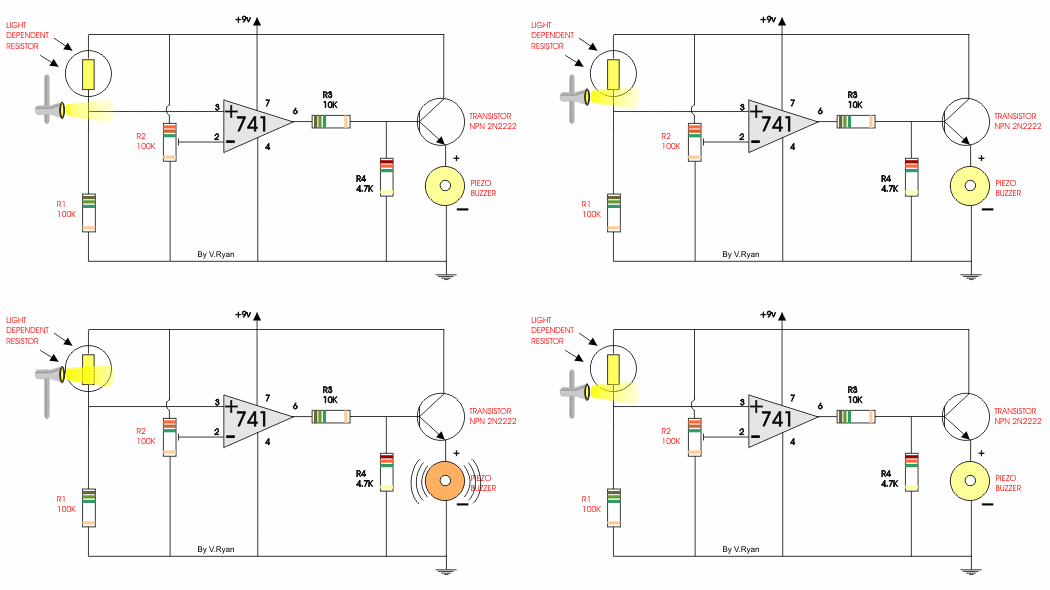
EXAMPLE CIRCUIT - LIGHT ACTIVATED ALERTER
The buzzer emits a tone when light falls on the light dependent resistor.
Resistor 2 controls the sensitivity of the circuit.

The 741 is working as a comparator and the piezo buzzer sounds when the output form the 741 goes
 ‘low’ or in other words, changes from a positive to a negative.


EXAMPLE CIRCUIT - DARK ACTIVATED ALERTER
This is a dark activated circuit, the reverse of the circuit above. Do you notice the difference ?

If you look carefully you will notice that resistor 1 and the LDR have changed positions.
Also, the inputs to the 741 are reversed.
Replace the LDR with a thermistor for a temperature circuit.


2 comments :

  1. http://www.technologystudent.com/elec1/opamp3.htm
    V. Ryan © 2002-09

    ReplyDelete
  2. really a nice project

    ReplyDelete

Copyright © Rough Record. Designed by OddThemes